I’m sure by now every MX5 or Roadster owner has done this mod, or it’s already been done by the previous owner of their car. However, in my case it wasn’t and gave me the opportunity to do a job that didn’t involve rust!
For those who don’t know, without the Flash to Pass modification pulling back on the indicator stalk to flash the main beams of the car only serves to illuminate the engine bay as the pop-up motors don’t engage at the same time. Making this mod allows the motors to pop-up when flashing. Its a really quick job, 30 minutes max and really satisfying.
Don’t for one second think that I have worked out what to do and how to do it on my own. The Internet already has a number of guides and I used this one from robinm on MX5Nutz and this one from JSeaman on the same site. One thing to note from robinm’s write up is that the link to the diode he uses seems to go the the wrong part. I chose to find the correct item https://www.maplin.co.uk/p/1n5408-3a-silicon-rectifier-ql87u rather than buy the one linked to directly.
Step one
As with all electrical work – Disconnect the car battery.
Next, remove the covers around the steering column. Differing from JSeamon’s guide, my cowl had four screws with one being deep inside the recess at the back left hand corner.
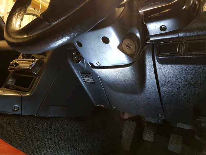
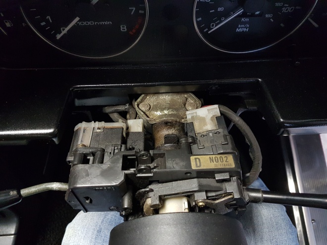
With all four screws removed the cowl comes apart very easily and moved out of the way.
Step two
With the cowl removed you can now see the white electrical connector we’re going to deal with.
On the underside of it there is a small tab which needs to be depressed in order for the connector to slide backwards.
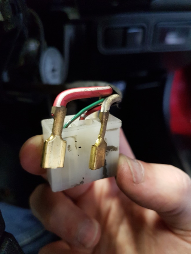
Step 3
Now we have access to the connector we can identify the two wires we need to connect. Find the red wire with a white stripe (lights) as well as the white wire with the black stripe (lamp motor) as these need to be removed from the main connector temporarily.
To remove them find a small screwdriver or flat blade and slide it in to the relevant block from the side opposite to where the wires go in. You should feel a small plastic tab, gently push down whilst pulling the wire from the other side and the spade connector should slide out quite easily.
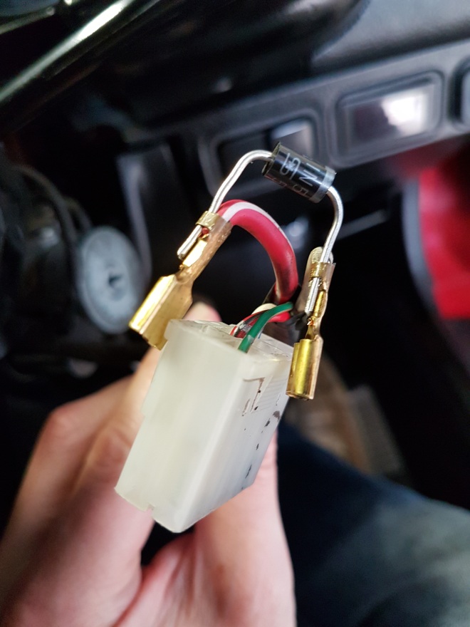
Step 4
Next we need to bridge the two connectors with our diode, so using the same tool used to remove the wired from the main connector slightly open up one tab that is gripping the spade to the wire’s plastic jacket.
Now slide the legs of the diode between the metal tab and plastic jacket before crimping tightly back up. It’s important to note the stripe that goes around the top of the diode’s body as this is the end which the current flows out of and this is the end that needs to go in to the motor (white wire) connector.
If the legs of the diode are too long just trim them slightly.
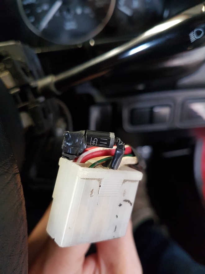
Step 5
I’m no electronics expert and didn’t feel as though it was a good idea to have the legs of the diode exposed so I wrapped some insulating tape around them before refitting the connectors back in to their original blocks.
Step 6
Push the main connector back in to it’s housing and test before replacing the cowling around the steering column. Once the battery is reconnected it should just be a case of pulling back on the indicator stalk and seeing the results of your handy work.